3D Printing & Scanning
Face Scan via Structured-Light (RevoPoint)
I scanned my face using the RevoPoint structured-light camera and the accompanying RevoScan software available in the lab. The scanner works by projecting a pattern of infrared light onto the subject and reading the deformation with a depth sensor, producing a dense point cloud that is then meshed.
Scanning Challenges
The main difficulty was hair. Structured-light scanners rely on finding consistent surface geometry, and hair produces a chaotic, semi-transparent surface that the algorithm struggles to reconstruct reliably. To get a clean result I chose to only scan my face - forehead to chin, excluding the hair above - and kept lighting conditions as even as possible to minimise specular reflections on skin.
Click and drag to rotate • Scroll to zoom • Right-click drag to pan
Post-Processing in Blender
The raw mesh exported from RevoScan (headmodified.stl) still contained
floating noise artefacts and thin geometry at the hair boundary. In Blender I:
- Removed noise islands using Select → Select All by Trait → Non-Manifold and manual cleanup
- Trimmed the ragged hair boundary to leave a clean face silhouette
- Added a solid "cap" to close the back of the face so the mesh is fully watertight - a requirement for 3D printing
The cleaned result was saved as headmodified2.stl.
Click and drag to rotate • Scroll to zoom • Right-click drag to pan
3D Print: Elephant–Face Hybrid
This object was designed as something that cannot be easily made by subtractive methods: the face geometry is embedded inside the curved surface of an elephant head, creating undercuts in every direction. A mill or lathe would require many setups with complex fixturing, and the fine facial detail would be lost. Additive manufacturing handles this natively.
Design Process
I downloaded an elephant model from GrabCAD (Elefant by werkel) and imported both it and the cleaned face scan
into Blender. After scaling and aligning the face to sit on the elephant's forehead
region, I performed a Boolean union to merge the two meshes, then exported as
elefantheadtoptop.blend (the Blender source) and as an STL for slicing.
Interactive 3D Model
Click and drag to rotate • Scroll to zoom • Right-click drag to pan
Print Attempts
Getting the orientation and supports right required three iterations. Each photo below shows all three prints side by side: black = Attempt 1, orange = Attempt 2, yellow = Attempt 3.
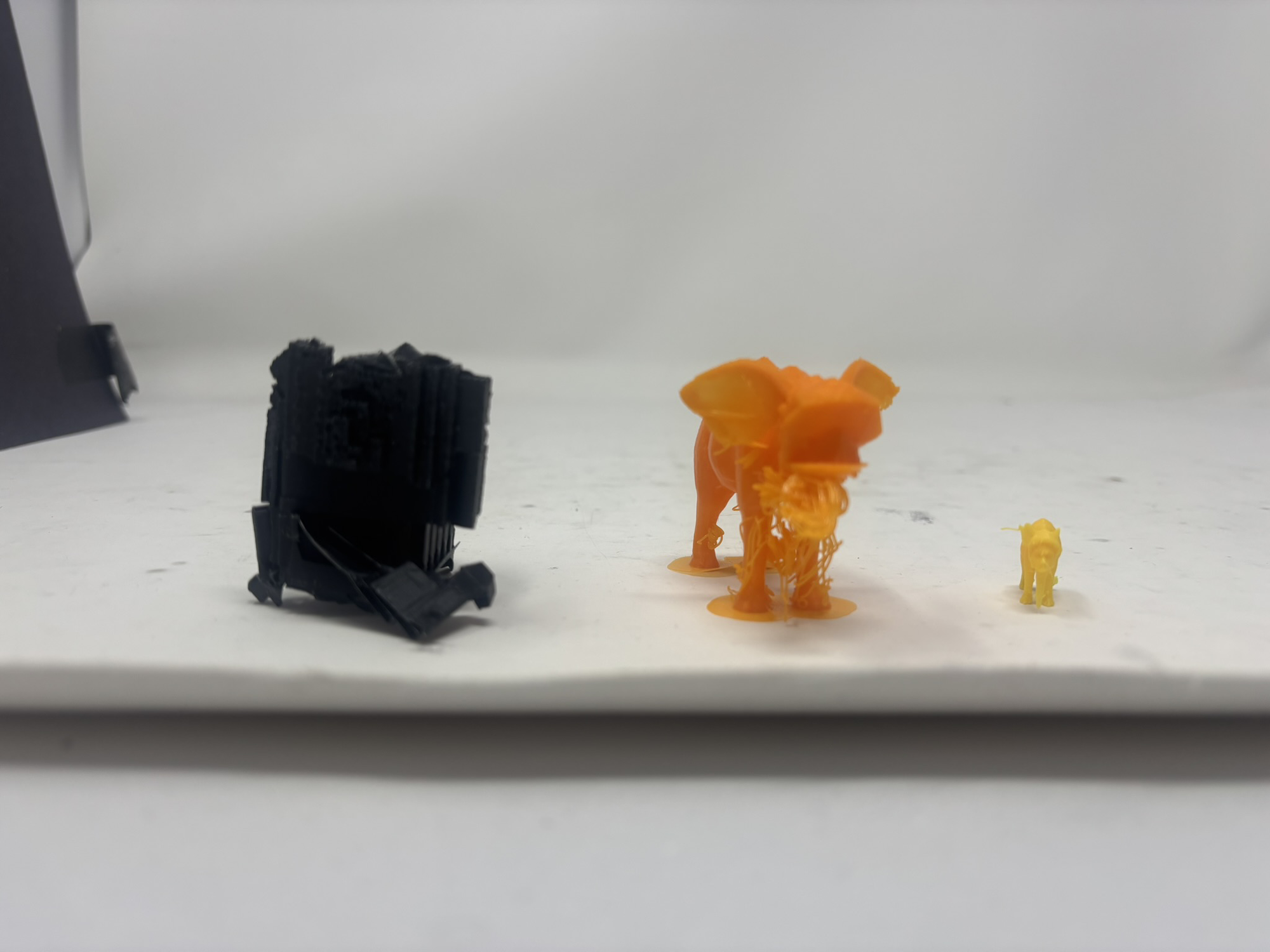
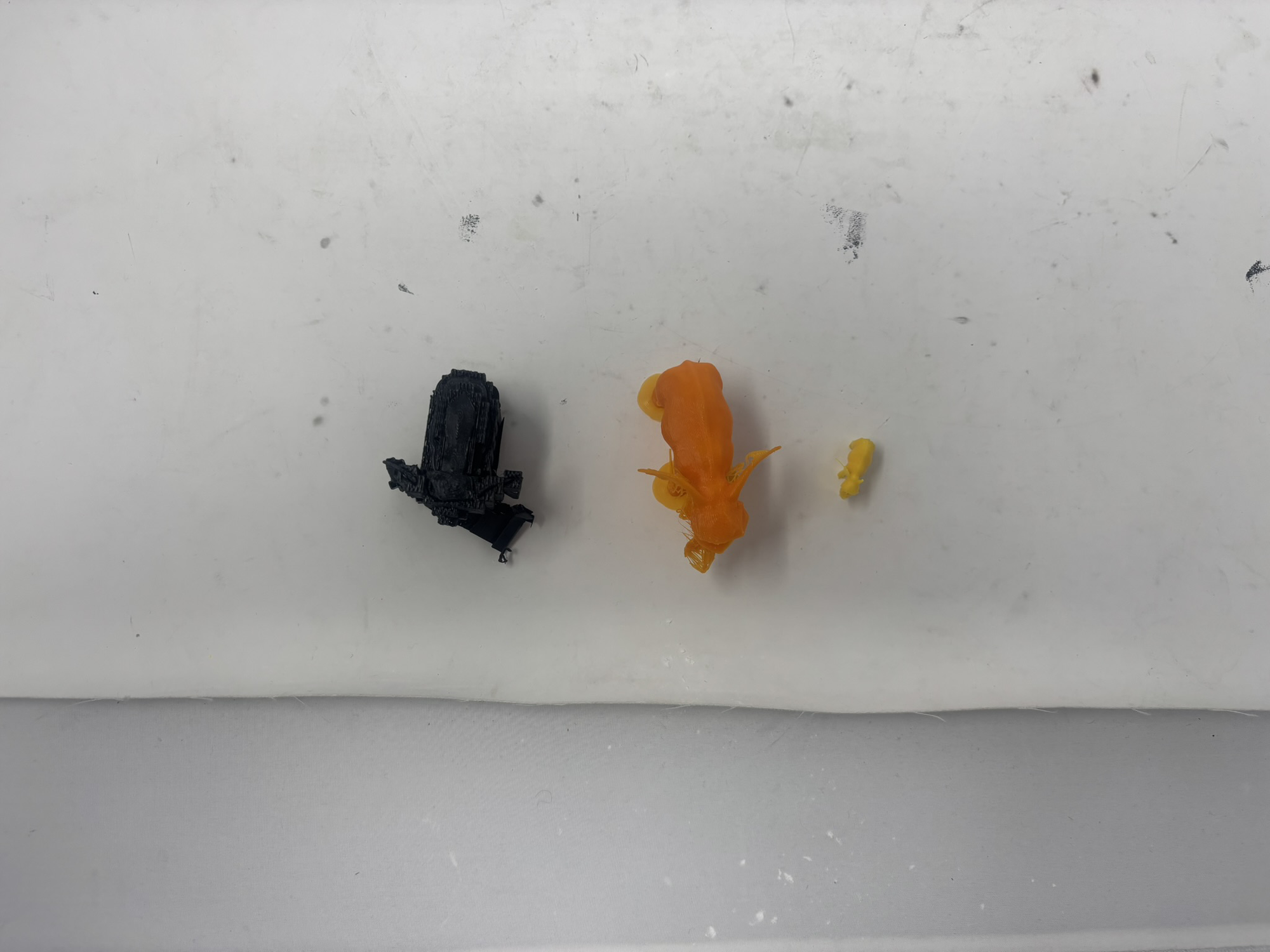
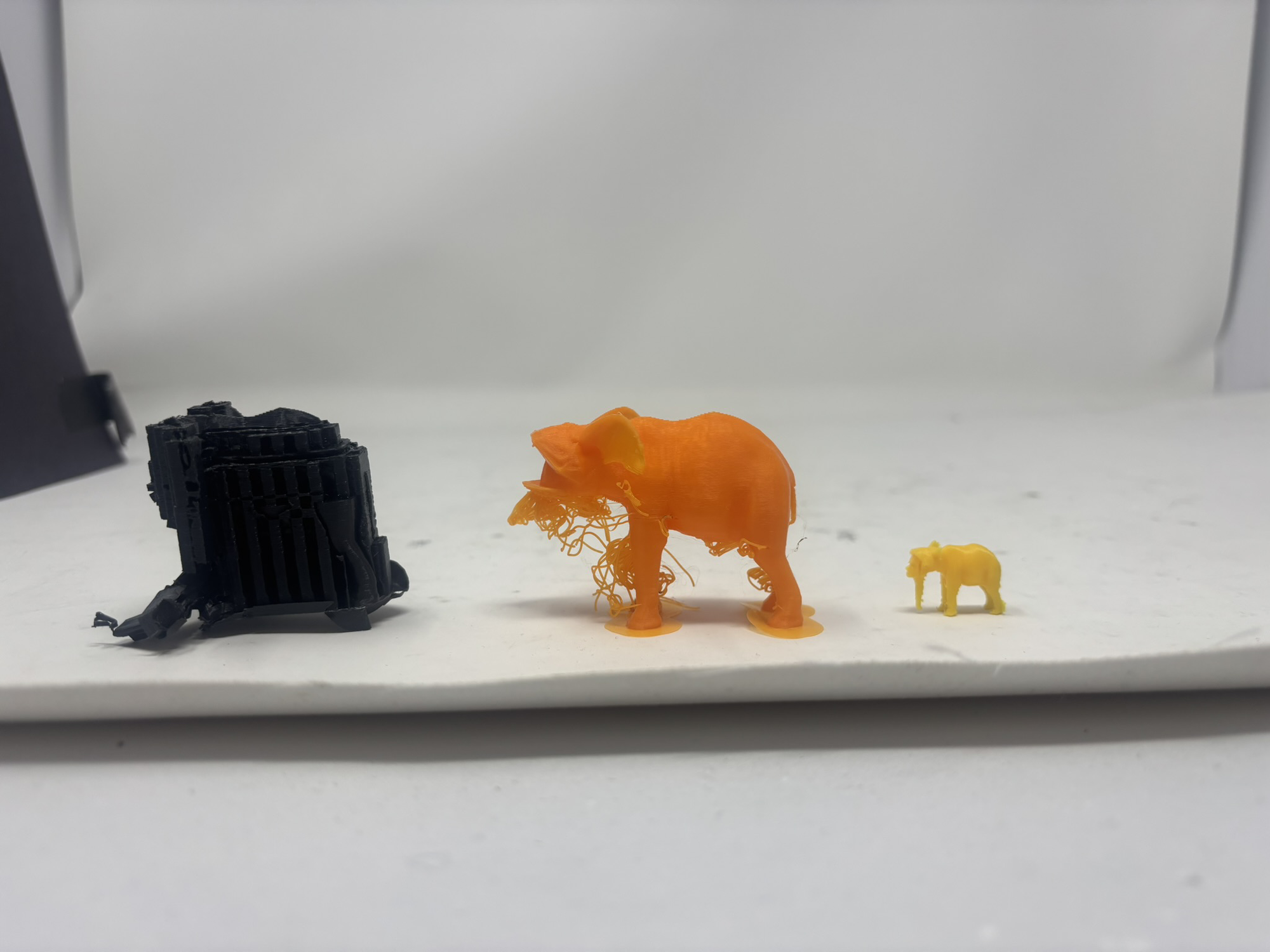
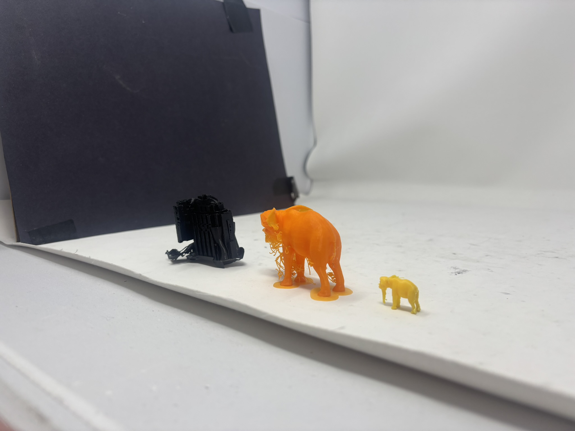
Attempt 1 (black, MK3): Naive first try - printed upright on its feet with full supports. The result was a mess.
Attempt 2 (orange, MK4): Switched to the better MK4 printer and printed on its feet with no supports. The MK4's improved bridging helped, but the underside geometry still caused problems.
Attempt 3 (yellow, MK3): Back on the MK3, but this time placed the elephant on its back and added full supports. Best result so far - the face detail is readable and the form holds.
Final Project: Drone from Scratch
My final project is to build a fully functional quadrotor drone from first principles - minimising tutorial-following in favour of trial-and-error learning. The goal is to deeply understand every subsystem: aerodynamics, motor control, power distribution, and flight stabilisation.
Philosophy
Rather than buying a kit or following a step-by-step build guide, I will attempt each subsystem independently, fail fast, analyse the failure, and iterate. Tutorials will only be consulted when I am genuinely stuck after exhausting my own attempts.
3D-Printed Structure
The primary frame and rotor guards will be 3D printed. The current CAD model covers the structural components I want to print; motor mounts, electronics interfaces, and sensor brackets will be added in subsequent revisions. A downloadable STL will be added here once the model is finalised.
Frame
Click and drag to rotate • Scroll to zoom • Right-click drag to pan
Rotor
Rotor model downloaded from the description of this YouTube video by TheFusionEssentials.
Click and drag to rotate • Scroll to zoom • Right-click drag to pan
Planned Extensions
- Arduino-based flight controller (custom PID implementation)
- Brushless motors with ESCs
- IMU (accelerometer + gyroscope) for stabilisation
- Ultrasonic / ToF sensors for altitude hold and obstacle avoidance
- Optional: pen-holder payload so the drone can write on a surface
Bill of Materials
Estimated BOM for the drone project. Prices are approximate and will be refined as the design develops.
| # | Component | Qty | Unit Price (est.) | Notes |
|---|---|---|---|---|
| 1 | 3D-printed frame & arms | 1 set | ~$5 (filament) | PLA or PETG, printed in lab |
| 2 | 3D-printed rotor guards | 4 | ~$2 (filament) | Protective shrouds around each propeller |
| 3 | Brushless motors (2204 or similar) | 4 | ~$8 each | ~2300 KV for 5" props |
| 4 | Electronic Speed Controllers (ESC) | 4 | ~$6 each | 20 A rated, BLHeli_S firmware preferred |
| 5 | Propellers (5" 3-blade) | 4 + 4 spare | ~$1 each | 2× CW, 2× CCW per set |
| 6 | Arduino Nano / Uno | 1 | ~$5 | Flight controller candidate; may migrate to custom PCB |
| 7 | IMU - MPU-6050 | 1 | ~$3 | 6-axis accelerometer + gyroscope |
| 8 | LiPo battery (3S, 1300 mAh) | 1 | ~$15 | Balance connector; lab charger compatible |
| 9 | Power distribution board (PDB) | 1 | ~$4 | Or custom PCB in later weeks |
| 10 | RC receiver (e.g. FlySky FS-iA6B) | 1 | ~$12 | Paired with a basic 6-channel transmitter |
| 11 | RC transmitter (FlySky FS-i6) | 1 | ~$35 | May share with lab unit if available |
| 12 | ToF distance sensor (VL53L0X) | 1 | ~$4 | Altitude hold / ground detection |
| 13 | Wiring, connectors, heat-shrink | - | ~$5 | XT30 / XT60 connectors for battery |
| 14 | M3 hardware (bolts, nuts, standoffs) | - | ~$3 | For mounting motors and electronics |
| Estimated Total | ~$120 | Before pen-holder payload | ||